 1 The final Fokker Dr.1 |
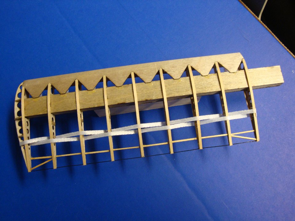 2 Starting with the wings, this is one-half of the lower wing. |
 3 The completed lower wing, with ribbon lacing and wingtip. |
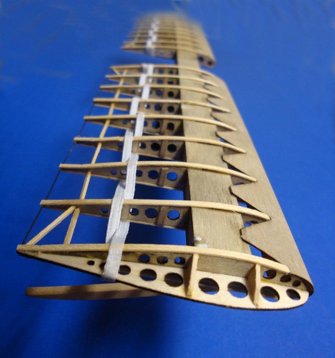
 4 Finished lower wing |
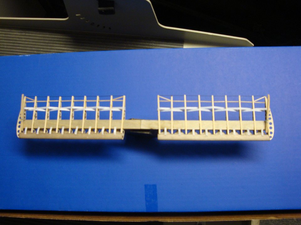
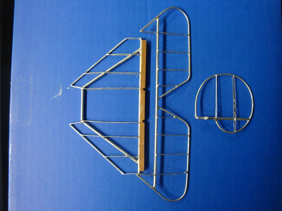
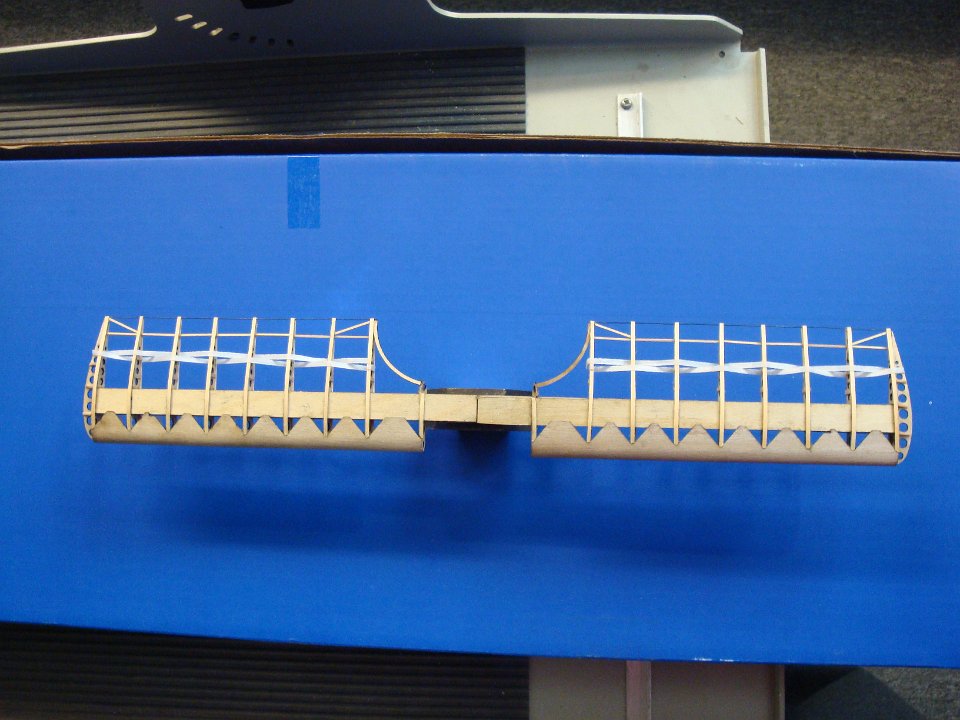 5 Finished middle wing. Note curved trailing edge. |
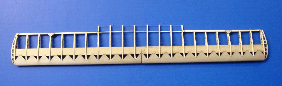 6 Upper wing before airleons. |
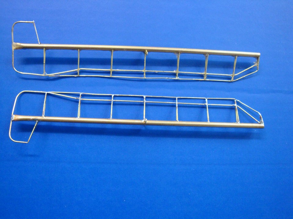 7 The brass airleons |
 8 Seven ply propellor. |
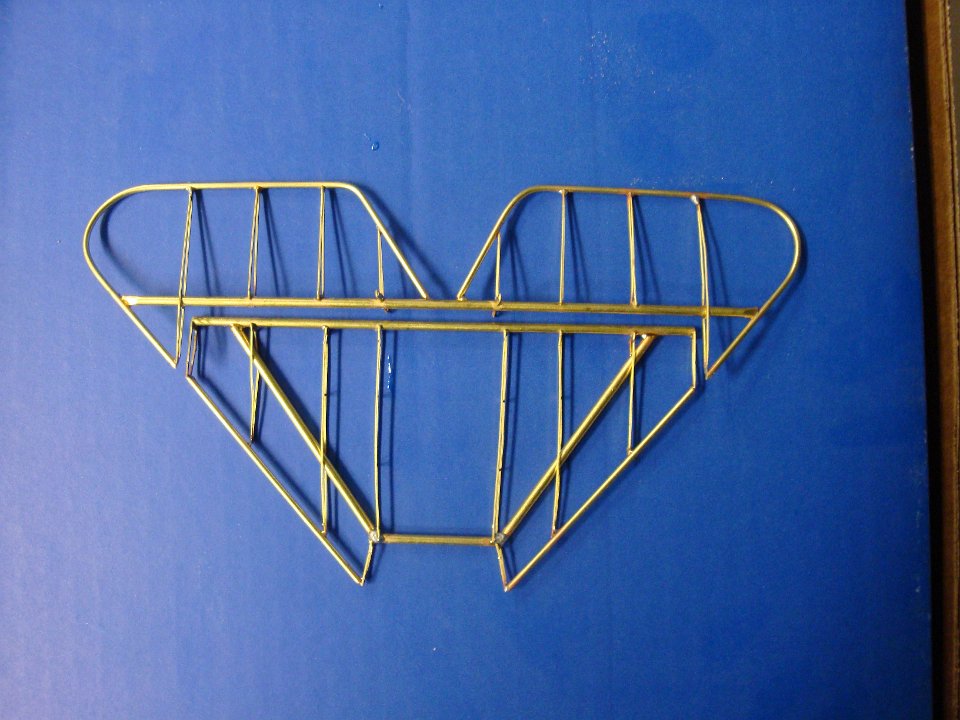
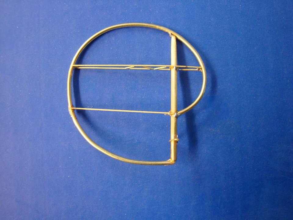
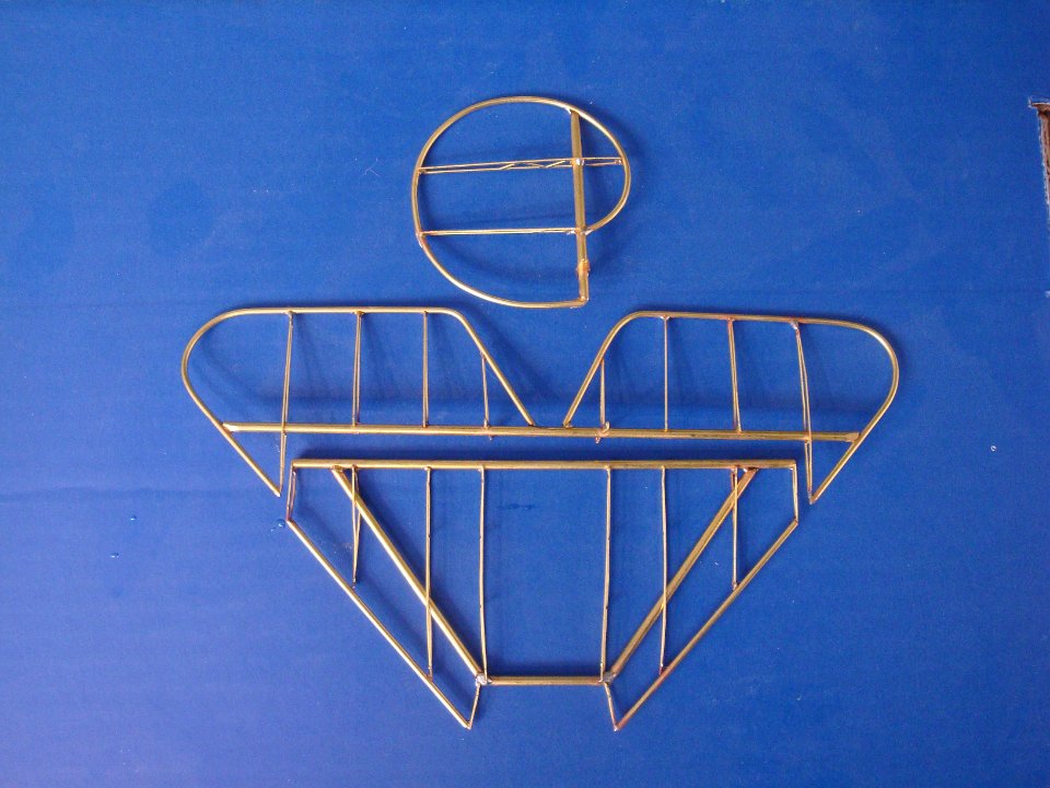
 9 The metal frame members before assembly. |
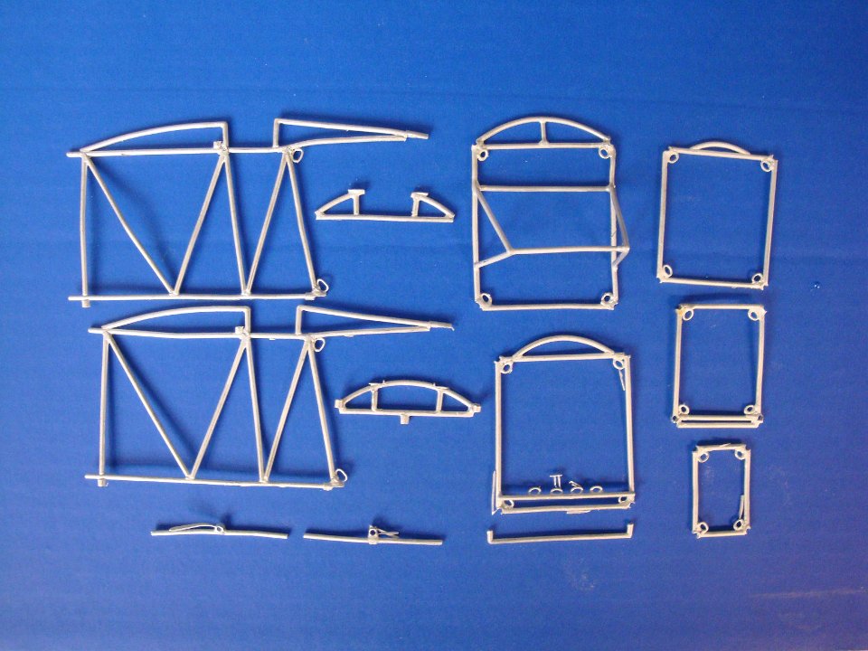
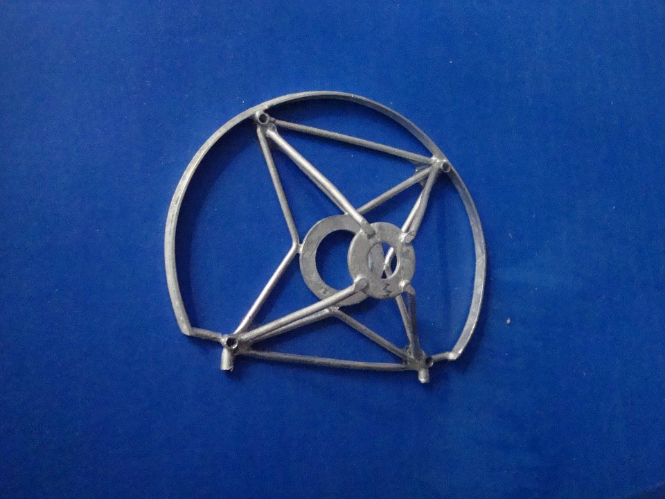 10 The assembled motor mount. |
 11 Adding the side members to the motor mount. |
 12 Each frame has a station in the assembly jig, furnished in the kit. |
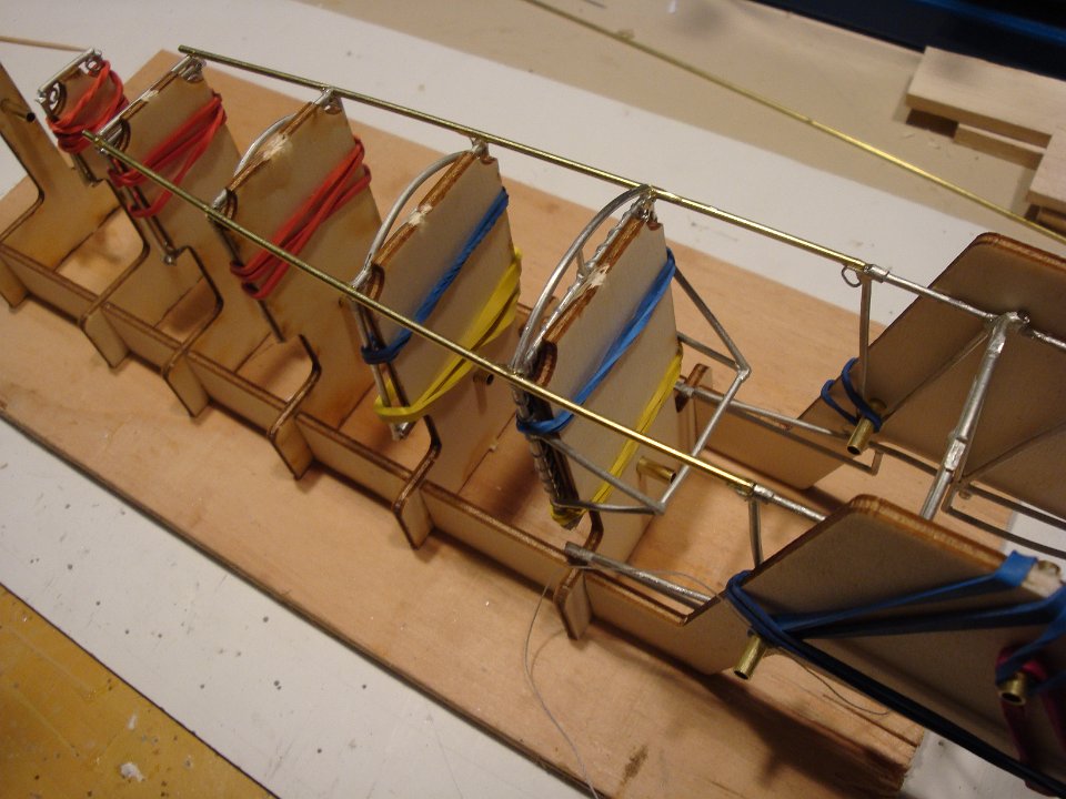
 13 The assembled fuselage, all metal, glued with epoxy. |
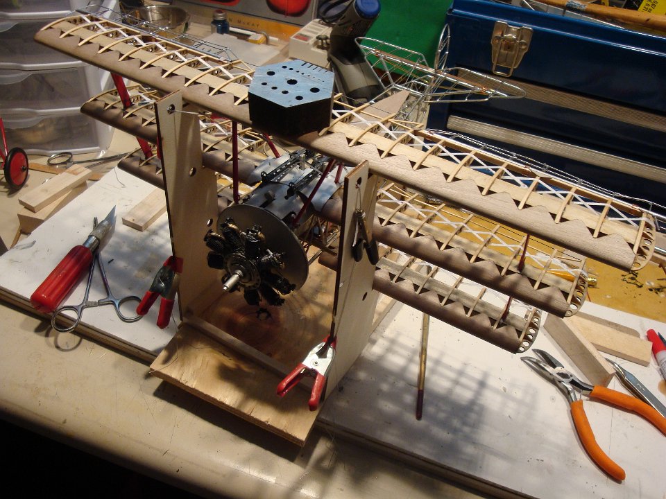
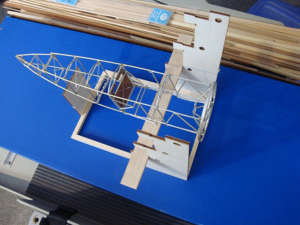 14 The assembly jig accomodates the assembled fuselage, using a wood member to act as the lower wing. |
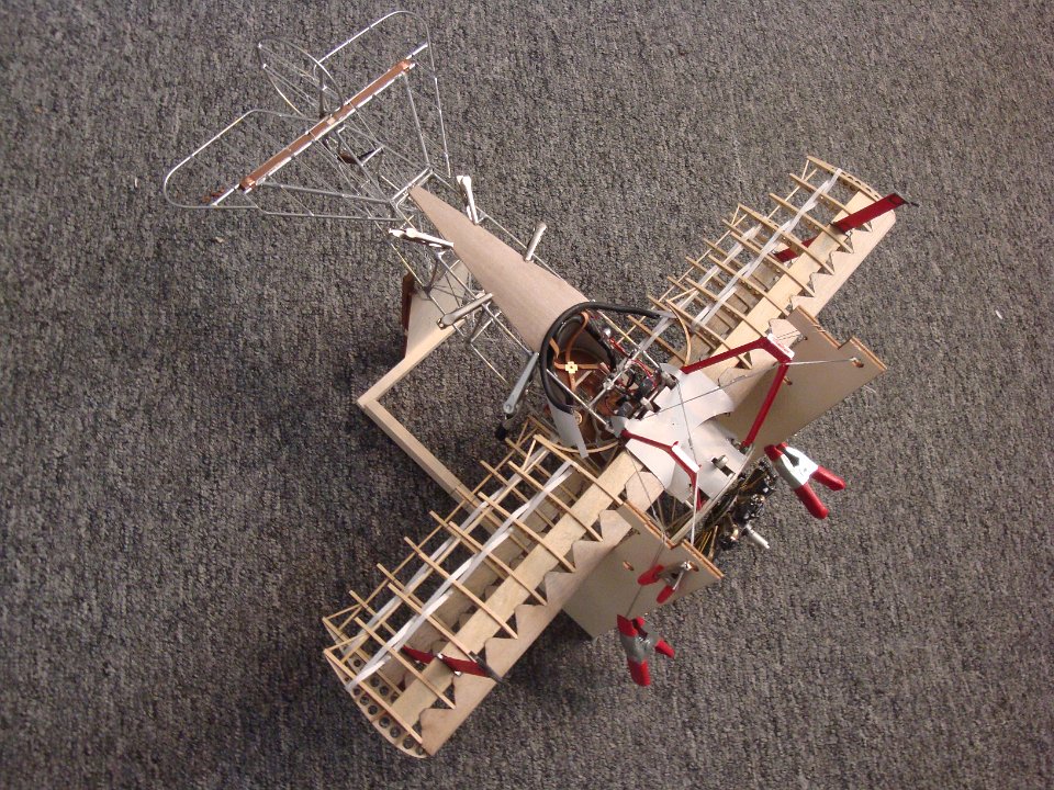
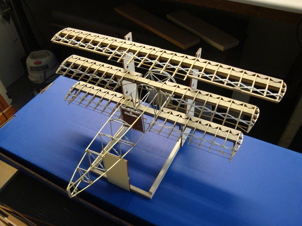 15 The three wings temporarily assembled to the fuselage, using the tiered assembly jig, which is critical to the final assembly. |
 16 The rudder control stirrups, together with the airleon control stick, showing the turnbuckles and the control cables. |
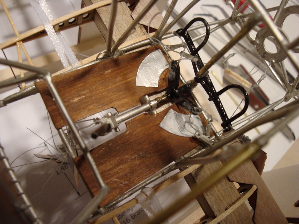 17 Here, the floor board has been installed over the control linkage. Note the heel strips on the floor boards. |
 18 The all-metal elevator and stabilizer. These assemblies were all soldered, since brass predominates. The kit recommendation is to use epoxy. |
 19 The elevator by itself, prior to installation with the stabilizer. |
 20 The rudder has the Fokker characteristic shape. |
 21 All of the tail components ready to install. |
 22 The wood member is formed by three pieces to form an 'H' shape to accommodate the elevator leading round edge, which will be attached to allow rotation. |
 23 The final tail assembly installed onto the fuselage. |
 24 Showing the metal support members under the fixed portion of the elevator assembly. |
 25 Again, a trial fitting of the wing assemblies. |
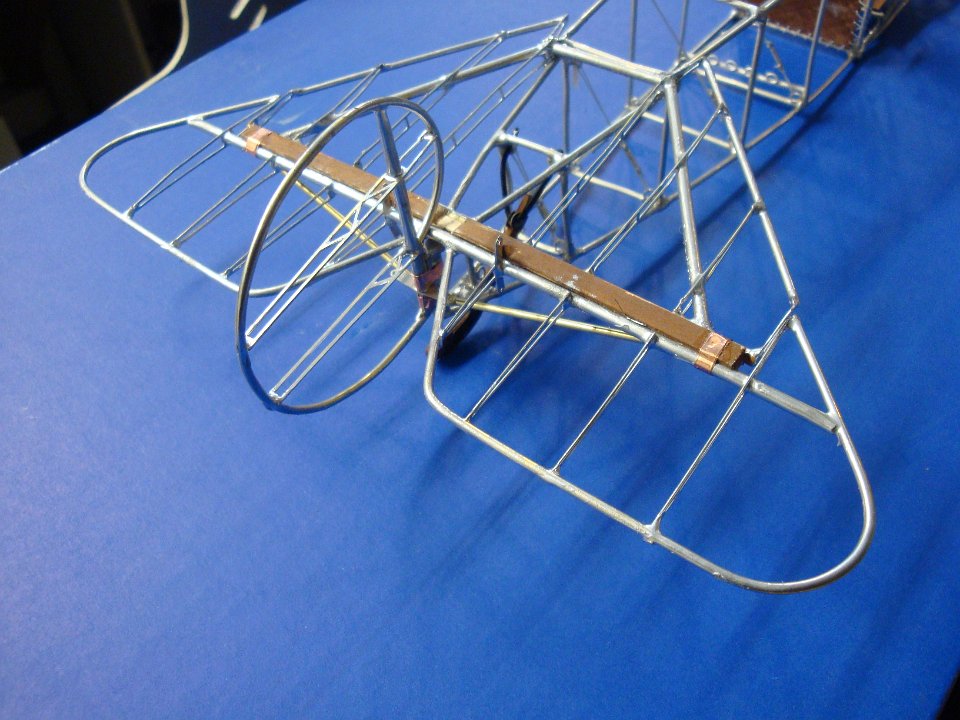
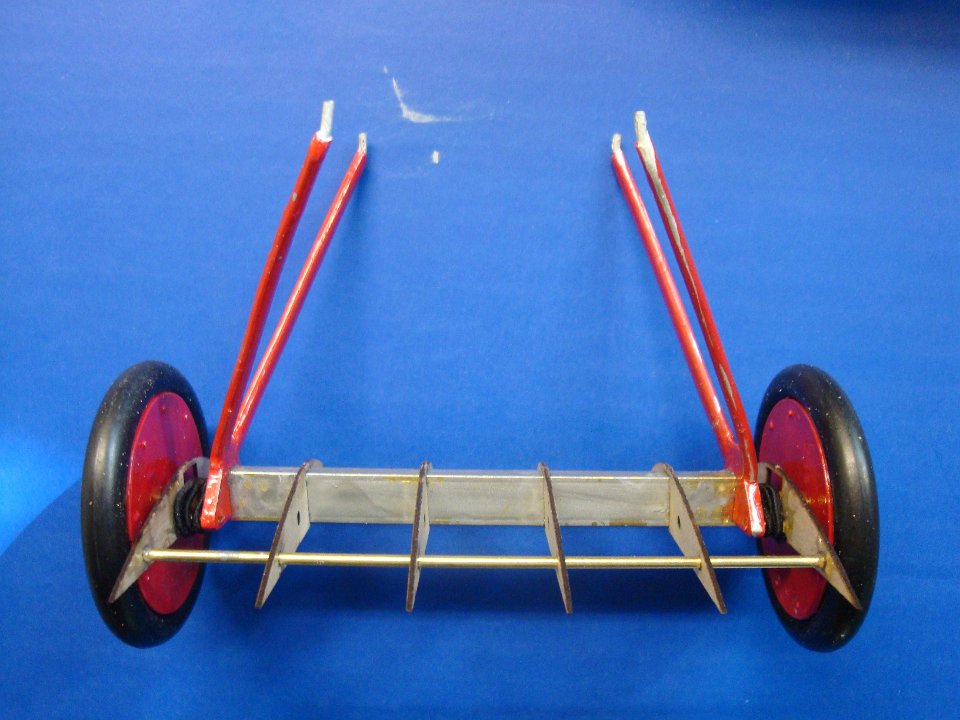 26 A novel landing gear assembly, providing an airfoil between the wheels. |
 27 The stress cabling is extensive in this model, emulating all that was used to stiffen the actual prototype airplane. Turnbuckles are in each and every cable. Note the control cabling leading to the tail section. |
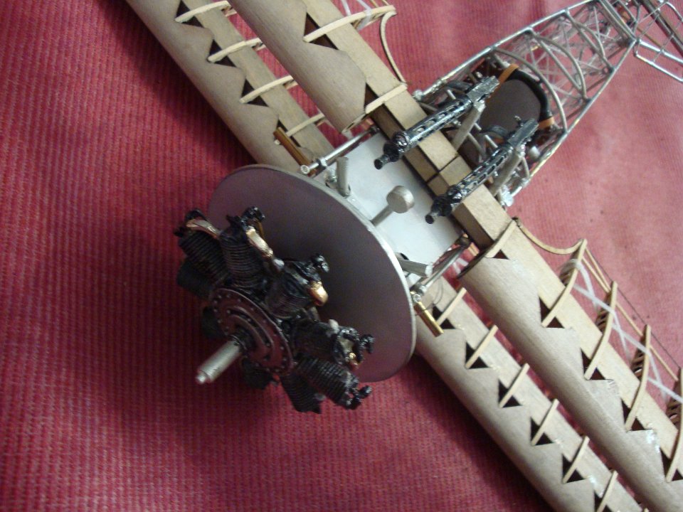
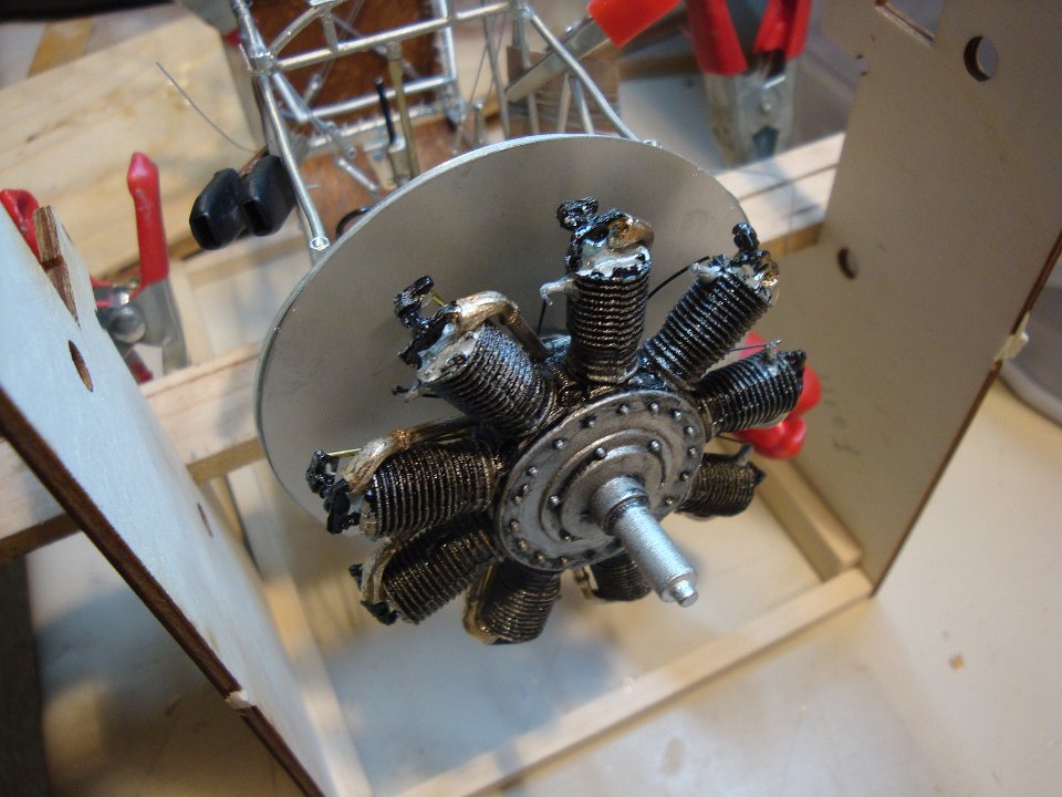 28 The engine is installed with the central drive shaft protruding back through the motor mount. Note that the radial engine itself rotates for air cooling, while the drive shaft remains stationary. |
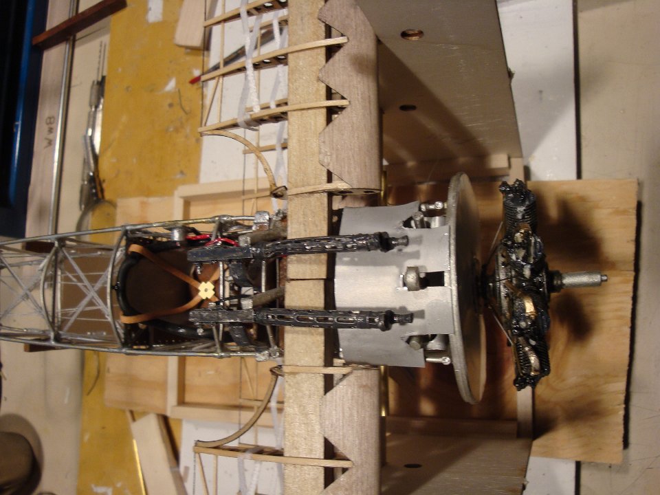
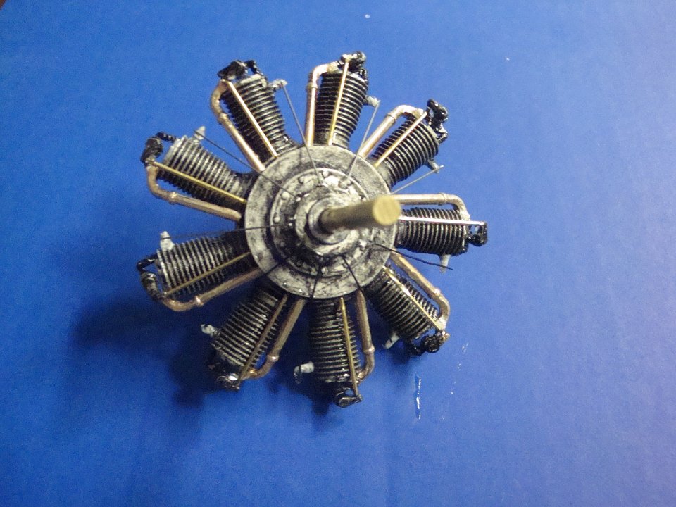 29 The engine from the rear, showing the protruding drive shaft. There is an intake manifold, valve push rod and ignition wire for each of the nine cyclinders. |
 30 The motor mount showing the protruding drive shaft through which all of the required fuel and magneto cabling is threaded. |
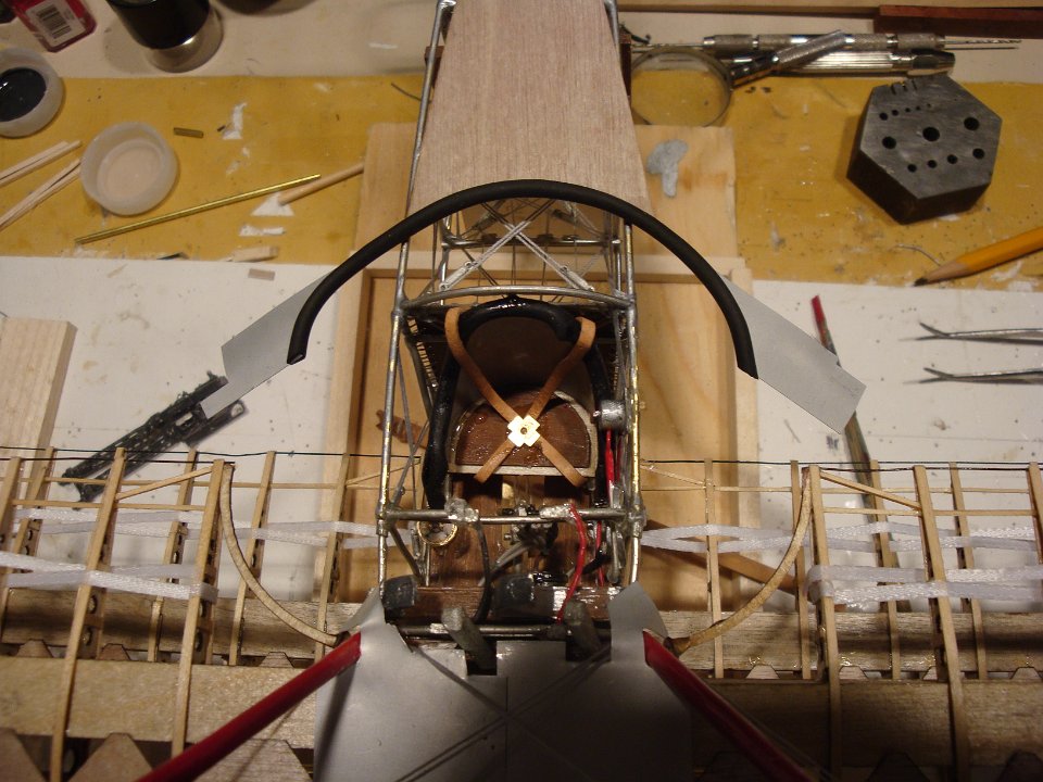
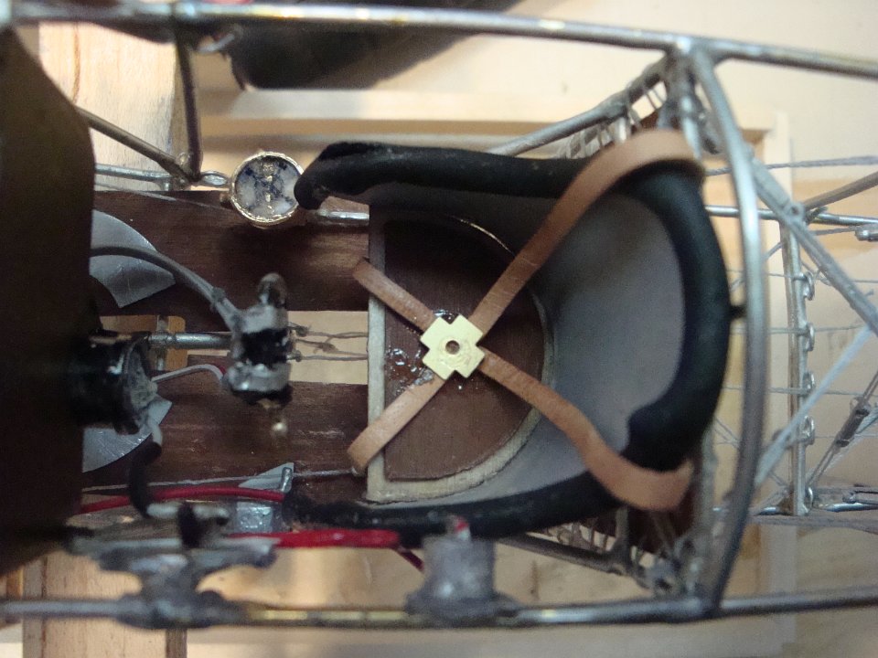 31 The cockpit is taking shape here, with the bubble level, magneto controls, stick and seat, complete with leather straps and buckle. |
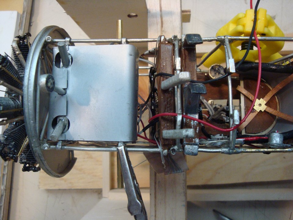 32 In this kit, the fuel tank is fabricated from internal members, covered with sheet metal exterior. In the Fokker dr.1, the fuel tank is divided in two compartments, to contain, the gasoline in one, and the castor oil in the other. Each has it's own fill tube as seen in this image. |
 33 After the entire fuselage is completed with controls and cabline, the lower wing is glued in place, using epoxy. Note the airleon control cabling wound upon a scrap wood. |
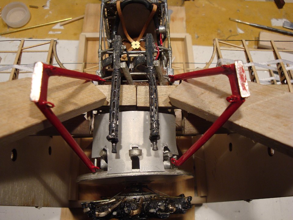
 34 The middle wing is next to be installed. In this image, the machine guns are fitted into place, but must not be glued until the sheetmetal covering and upper wing struts are installed. |
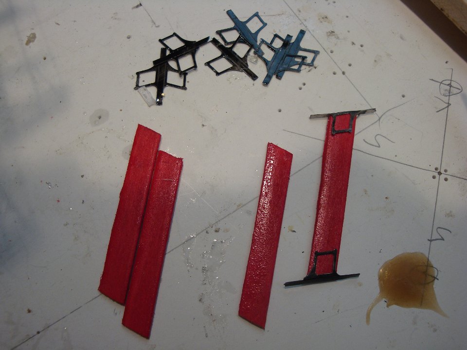 35 The four inter-wing struts are shaped into air foils and the metal fasteners are glued on each end. These metal pieces will then be wrapped around the wing beams for added strentgh. |
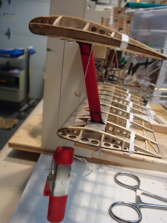 36 The Fokker design utilizes a central rectangular wooden beam for rigidity, eliminating the need for the many stress cables utilized in other planes of the period. |
 37 Sheet metal cowling is added here, again with the guns temporarily fitted in place. |
 38 It is necessary to install the upper wing struts at this point, since their attachment points will be covered by additional sheet metal cowling to be applied next. The stress cabling points at the base of the struts must also have the cables installed as the eyes on the struts will be covered by sheet metal. |
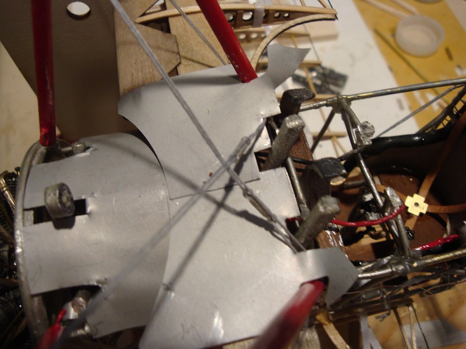 39 The sheet metal cowling is installed here, and the stress cabling is shown also. |
 40 The final pieces of sheet metal are epoxied to the rubber cockpit lining prior to epoxing the metal in place to complete the cockpit. |
 41 A plywood cowl is applied to the rear of the cockpit to provide the curved surface for the fabric used in the actual plane. |
 42 The upper wing is installed together with the struts. Both the metal interior struts and outer wooden struts are epoxied at the same time. |
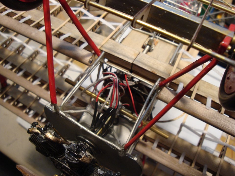 43 Underneath view of the extensive wiring and tubing utilized to make the kit as realistic as possible. |
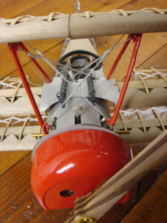
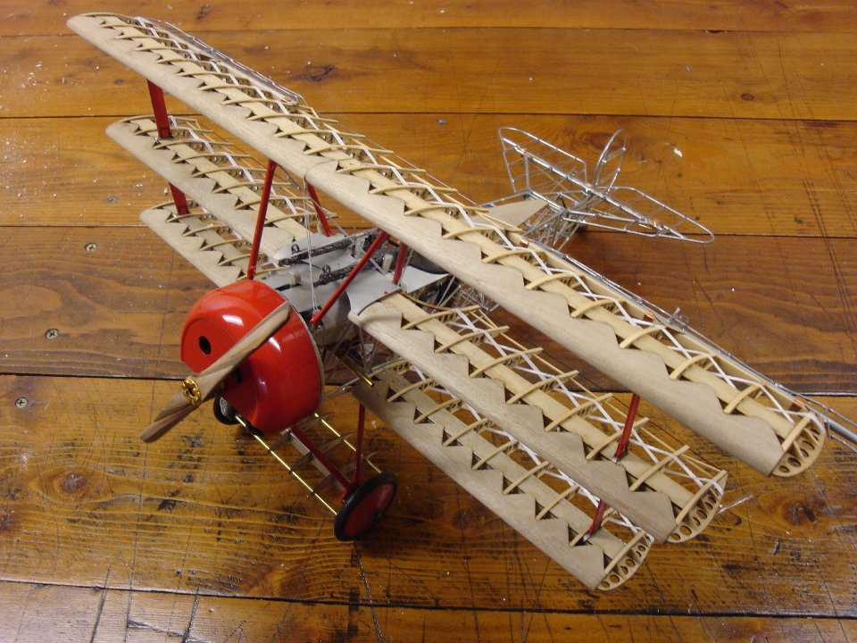 44 The finished kit, showing the red engine cowl, painted to match the 'Red Baron' Richthofen airplane. |